top of page


Example of Hall sensors in action
Learn about Hall sensors!
History of Hall Sensors

In 1879, Edwin Hall discovered the Hall effect.
In his experiment, he placed a strip of conducting material in between magnet poles with the magnetic field lines being perpendicular to the strip surface plane.
Hall observed that there is a voltage developed perpendicular to the current flowing direction and concluded that the magnetic field exerted forces on the flowing electric charge.
How does it work?
The Lorentz Force
When a charged particle (e.g. electron) moves through a magnetic field, it experiences a force perpendicular to its traveling velocity and the magnetic field direction. This force is known as the Lorentz force.
The Lorentz force is described by the following relation:
F = q(v x B)
Where q is the charge of the particle, v is the electron velocity, B is the magnetic field, and F is the resulting force felt by the electron under the influence of a magnetic field.

The Hall effect
As an electric current flows through a conducting material in the presence of a magnetic field, the magnetic field induces the Lorentz force upon the moving electrons.
This deflection of electrons results in the accumulation of electrons on one side of the conductor, thereby inducing a potential difference between both sides of the conductor. This potential difference can be measured and is known as the Hall voltage.
Types of Hall effect sensors
Linear Hall Effect Sensors
Linear Hall effect sensors uses the Hall effect to measure magnetic fields. When current flows through a Hall sensor, which is typically made of Gallium Arsenide or Indium Arsenide,a voltage difference is generated across the sensor. The output voltage of linear Hall effect sensors is proportional to the magnetic field strength. The output is typically analog that can be processed further using converters or directly interfaced with microcontrollers.
Hall effect sensors that are integrated into a module often come equipped with a tiny bulb to indicate the presence of a current flow. Let us check this out on the 44E sensor, in the image on the right, using a conventional bar magnet The power (red) and ground (black) are connected up. There is no use for a microcontroller for this test other than to provide a power supply.

Examples of Hall effect sensor modules.
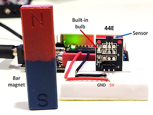
When there is no magnetic field near the sensor, the built-in bulb does not light up.
When the North pole of the bar magnet is brought close to the back of the Hall sensor, the built-in bulb lights up. Thereby confirming the presence and polarity of the magnetic field. When the South pole of the bar magnet is brought close to the back of the Hall sensor, the built-in bulb does not light up.


Likewise, bringing the North pole of the bar magnet close to the front of the Hall sensor does not result in the built-in bulb lighting up, whereas bringing the South pole of the bar magnet lights up the built-in bulb.
Three-Axis Hall Magnetometers
Three-axis Hall magnetometers are mostly used for applications that require sensing and measuring magnetic fields in three dimensions.
Some example applications of three-axis Hall magnetometers include compasses, joysticks, motion tracking and automation, and etc.
The phone magnetometers that we used to measure the Earth's magnetic field in MagnetiSiM 2022 are in fact an example of three-axis Hall effect sensors.
Automotive Systems and Magnetic Switches
Hall effect sensors are often found in cars for various uses. For instance, the safety feature of modern cars alerts the drivers of passengers who have yet to strap in. A Hall effect sensor within the seat belt buckle is activated when the seat belt latch pushes a magnet towards the Hall effect sensor. This induces a Hall voltage which will be detected.
More detailed explanation here.
Cooling Fans
A common application of Hall effect sensors can be found in the rotating parts, such as cooling fans equipped in computers. Please note that by dismantling such fans, you will risk permanently damaging it. We advise against doing so unless you have a fan which you wish to discard.


Removing the blades from its frame reveals the components which help the fan rotate. For instance, there are the obvious coils of wire which are electromagnets.
Below the coils lie the integrated circuit which controls the coils to facilitate the rotation of the fan. Within the integrated circuit lies the Hall sensor which is tasked to detect the generated magnetic field and to keep the fan on constant rotation.

bottom of page