

Example of Hall sensors in action
Example of Hall sensors in action


Tabletop games such as air hockey or even arcade games make use of Hall sensors to improve the user experience. For instance, the game puck approaching a goal post or any critical region of the game table triggers the illumination of the decorative lights and sounding of certain victory tunes. Here, we demonstrate a simple setup that mimics such systems, with the use of Hall effect sensors.
By making use of a magnet as a puck to travel along a track that contains Hall effect sensors, the magnetic puck triggers the Hall effect sensors. In turn, the LEDs connected to each Hall effect sensor responses accordingly.

Items used:
Power supply (UNO and batteries)
3 Hall effect sensors
3 LED (red, yellow, green)
1 Magnet (ring magnet)
1 Breadboard
3 Resistors (220 Ohms)
Adhesives (hot glue gun)
Jumper cables (F/M and M/M)
Cardboard (track and scoreboard)
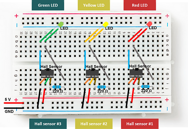
In this example, we make use of three Hall sensors, each connected to a LED bulb in series. This is how such a Hall sensor-LED pair is connected.
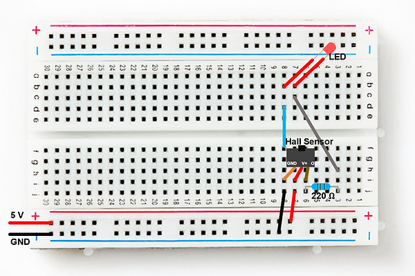
Depending on the number of Hall sensors and LEDs you want to implement, assemble more of such circuits in parallel to one another. Feel free to add as many LEDs as you want, or even tune the LED brightness by changing the resistor.
To be able to mount the Hall sensors and LEDs onto the track and scoreboard respectively, make sure to connect them to the breadboard with F/M jumper cables. This gives us some distance to work with.

Once it is verified that the Hall sensor-LED pairs are working as they should - i.e. responses when a magnetic field is brought close to them - we can proceed to mount the Hall sensors on the bottom of a cardboard track with adhesives. Do note to test if the cardboard tracks are thin enough for the Hall sensors to be able to sense the magnetic field of your puck magnet.

Next, attach the LEDs to the scoreboard, which is simply a thin piece of cardboard with slits to stick the LEDs through.

Check that all works well and we’re done!
Types of Hall sensor modules and their outputs
Two types of Hall sensor modules were used in this simple demonstration here.
Hall sensor #2 & #3 - YWRobot Hall sensor v2 module
Hall sensor #1 - 44E module

When the magnet is on top of Hall sensor #1 44E module, it prevents the output current flow and the Red LED is unlit. But as the magnet moves away from the Hall sensor #1 zone, the current flow is recovered, and the Red LED is lit.
When the magnet is on top of Hall sensor #2 & #3 YWRobot Hall sensor v2 module, the output current flows and both the Yellow and Green LEDs are lit respectively. At the same time, the Red LED remains lit.
This exercise illustrates how Hall sensor module outputs can operate differently. We would like to emphasize that the specifications of each purchased Hall sensor module should be studied and understood prior to implementation.

Some points for consideration in the setup’s design
-
Number of Hall sensors can be varied
-
Brightness of the bulbs can be manipulated with resistors - higher resistance gives a dimmer illumination
-
Types of Hall sensor outputs can be varied
-
Could have more than one LED per Hall sensor
-
Could include other Hall sensor-activated devices such as buzzers or alarms, and even a servo for a trap door
-
Study the relationship between the puck magnet and Hall sensors - what is the effective distance from a Hall sensor in which the puck magnet activates the Hall sensor?
-
Type of magnets - e.g. would a disc magnet work better than this ring magnet? How different would they be? How would the size of the magnet affect this device? Would a typical fridge magnet work?
-
Make use of the microcontroller
-
Better overall presentation e.g. could conceal the breadboard and add a switch